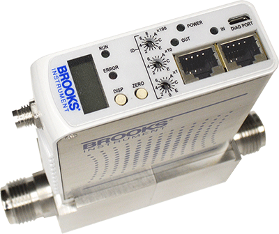
In this two-part blog series, we will first explore the architecture and performance characteristics of the EtherCAT® protocol. Then we will examine how Brooks leverages the real-time data acquisition capabilities of EtherCAT® in the GF100 Series MFCs.
Enhance Operational Performance & Value of GF100 Series MFCs
In many advanced manufacturing applications, there is a growing demand for the kind of high-speed, flexible machine communications supplied by Ethernet-based bus architectures.
EtherCAT® is an Ethernet-based communication protocol introduced in 2003. A recognized international standard since 2007, EtherCAT® provides exceptional performance for automation applications requiring real-time information and rapid reaction times.
Mass flow controller (MFC) technology can make sophisticated use of these capabilities. Protocols such as EtherCAT® offer the opportunity to enhance how critical MFC diagnostic and performance information is shared with, and used by, higher-level machine control systems. These are key reasons why Brooks Instrument introduced the semiconductor implementation of the EtherCAT® interface on its GF100 Series product platform.

How EtherCAT® Works
EtherCAT® uses a master/slave architecture as well as a processing “on the fly” principle to ensure real-time capabilities without delays. The EtherCAT® master sends a telegram that passes through each node as it moves downstream. Each slave device reads the data “on the fly” and adds its data to the frame. This unique technology allows a slave node to receive and forward an EtherCAT® message before the node processes the data, which means the information can be spread at a much faster pace, reducing response time. Once the last node detects an open port, the message gets sent back to the master.
By connecting the last node in the series back to an Ethernet port in the master device, this line topology configuration can be converted to a ring topology. The ring topology enables redundancy, ensuring that if there is a malfunction in the system, such as a broken cable, up-time is maximized and communication continues. This can be critical in systems with short cycle times so that processes can continue to run smoothly with minimal interruption.
 Source: EtherCAT® Technology Group
Each slave device reads the data "on the fly" and adds its data to the frame.
High Speed Data Exchange
PDO, or process data objects, are variables that are continuously transferred between the slave and the master in a high-speed data exchange. During network configuration, the user must configure the data to be exchanged. RxPDO Mapping defines the data that is sent from the master to the device and TxPDO Mapping defines the data that is sent from the device to the master.

The Brooks GF100 Series MFC with EtherCAT® defines a default PDO mapping for each device profile that the user can select, or a flexible PDO mapping which can be configured with up to 10 objects that must have the appropriate PDO access permission. Examples of PDO objects that can be mapped include active exception status, as well as flow, pressure and temperature readings.
Mapping an object requires the user to specify the object’s index, sub index, and size in bits in the PDO Mapping object. Objects with a data type that is not a multiple of 8 bits may require that a “pad” object be included so that the next object starts on an 8-bit boundary. It is best practice to group objects that are not a multiple of 8 bits so that only one “pad” is required, as the “pad” object counts as one of the 10 objects that can be configured. Configuring and assigning a flexible PDO allows for less network traffic and a more simplified system, eliminating metrics that are not applicable for a given application and allowing the user to focus only on the most crucial system attributes.
Now that we understand the EtherCAT® messaging architecture, our next blog post will examine the way this architecture is used by the GF100 Series to capture and communicate a range of error and exception messages to the automation control system.
Continue to Part 2
More on GF100 Series MFCs with EtherCAT®